
Incremental vs Absolute Encoders: Choosing the Right Type for Motion Feedback
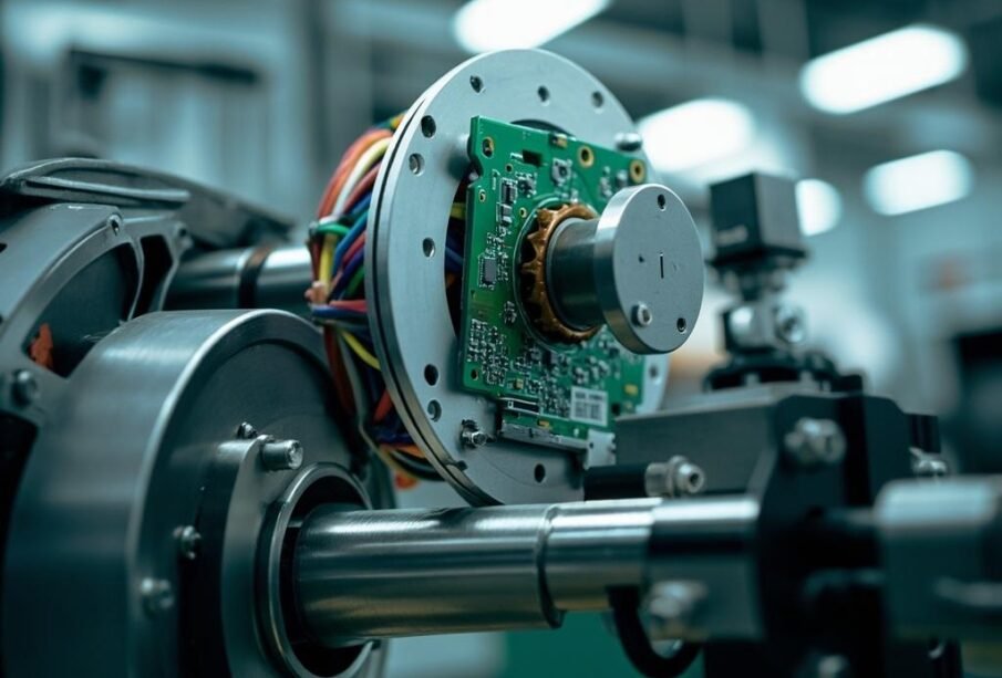
When designing precision motion control systems, selecting the appropriate encoder type is critical for achieving optimal performance, reliability, and efficiency. Encoders serve as the fundamental sensing devices that convert mechanical motion into electrical signals, enabling precise position and velocity feedback for motors, robotics, CNC machines, and automation equipment. The two primary categories of rotary encoders—incremental encoders and absolute encoders—offer distinct operational characteristics, advantages, and limitations that make each suitable for specific applications. Understanding the fundamental differences between these encoder types, their working principles, and their respective strengths is essential for engineers, designers, and technicians who seek to implement effective motion feedback systems in industrial, commercial, or research environments.
Understanding Rotary Encoders: The Foundation of Motion Feedback
Rotary encoders are electromechanical devices that monitor rotational movement and generate digital signals corresponding to shaft position and speed. These devices play a pivotal role in closed-loop control systems, where they provide real-time feedback that allows controllers to adjust motor behavior, maintain precise positioning, and ensure accurate velocity regulation. The choice between incremental and absolute encoding technology significantly impacts system complexity, cost, wiring requirements, and overall performance characteristics.
Encoder technology has evolved substantially over the past several decades, with advancements in optical sensing, magnetic sensing, and capacitive sensing methodologies enabling higher resolution, improved durability, and enhanced environmental resistance. Modern encoders can achieve resolutions ranging from a few pulses per revolution to thousands or even millions of counts per revolution, catering to applications demanding anything from simple speed indication to sub-micron positioning accuracy.
Incremental Encoders: Operating Principles and Characteristics
How Incremental Encoders Work
Incremental encoders generate output signals in the form of discrete pulses as the shaft rotates, with each pulse representing a specific angular increment. The fundamental sensing mechanism typically involves a coded disc with alternating transparent and opaque segments that interrupt a light beam from an LED source, creating pulses detected by phototransistors. The output consists of two square wave channels—Channel A and Channel B—that are phase-shifted by 90 electrical degrees, enabling direction detection through quadrature signaling.
The number of pulses per revolution (PPR) determines the basic resolution of an incremental encoder, with common values ranging from 60 PPR for low-resolution applications to 10,000 PPR or higher for precision positioning systems. Many incremental encoders also include a third channel, known as the index or Z-channel, which produces a single pulse per revolution at a reference position. This index pulse serves as a mechanical reference point that systems can use for homing routines, index counting, and position initialization.
Advantages of Incremental Encoders
Incremental encoders offer several compelling advantages that have sustained their widespread adoption across numerous industries:
- Simpler construction with fewer electrical connections compared to absolute encoders, typically requiring only two or three output channels
- Lower cost due to simpler manufacturing processes and reduced component complexity
- Higher maximum pulse rates enabling excellent speed measurement capabilities and fast response times
- Compact physical size making them suitable for space-constrained applications
- Wider availability with numerous manufacturers offering standardized products across various form factors
- Established interfacing standards with common output types including push-pull, open-collector, and line-driver configurations
Limitations and Considerations
Despite their advantages, incremental encoders present certain limitations that designers must carefully consider. The most significant drawback is their inability to retain position information when power is removed. Since incremental encoders only generate relative pulses, the controller must maintain an internal position counter that gets reset upon power loss. This characteristic necessitates homing sequences at system startup, which can be time-consuming in multi-axis systems or problematic in applications where absolute position must be known immediately after power restoration.
Additionally, incremental encoders are susceptible to counting errors if pulses are missed due to electrical noise, signal degradation, or mechanical vibrations. Implementing proper shielding, differential signaling, and noise filtering becomes essential in electrically noisy industrial environments to ensure reliable operation.
Absolute Encoders: Multiturn and Singleturn Technology
Fundamental Operating Principle
Absolute encoders represent position information using unique binary codes for each distinct shaft position, eliminating the need for external counters or position tracking. Unlike incremental encoders that require motion to generate information, absolute encoders provide instant position feedback at any time, including immediately after power-up. This fundamental difference in operating principle has profound implications for system design, reliability, and capability.
The coded disc in an absolute encoder contains multiple concentric tracks, with each track representing a different bit of the position word. These tracks use specialized coding patterns—commonly Gray code or binary code—that ensure adjacent positions differ by only one bit, minimizing errors from misalignment between read heads. The number of tracks directly corresponds to the encoder’s resolution, expressed in bits: a 12-bit absolute encoder provides 4,096 unique positions per revolution, while a 25-bit encoder offers over 33 million positions.
Singleturn versus Multiturn Absolute Encoders
Absolute encoders are categorized into two primary types based on their measurement capability:
- Singleturn absolute encoders provide unique position information within a single 360-degree rotation. After completing one revolution, the position code repeats. These encoders are ideal for applications where the shaft never exceeds one full rotation or where external gearing provides multi-revolution information.
- Multiturn absolute encoders incorporate additional mechanisms—typically gear-driven contact coders or electronic counting circuits—that track the number of complete revolutions. These encoders can report both position within a revolution and the total revolution count, providing true absolute positioning over extended ranges.
Communication Protocols and Interfaces
Absolute encoders typically employ serial communication protocols rather than simple pulse outputs. Common interfaces include:
- SSI (Synchronous Serial Interface) – A clocked synchronous protocol widely used in industrial automation
- BiSS (Bidirectional Synchronous Serial) – An open protocol offering higher speeds and additional features
- EnDat – Heidenhain’s proprietary protocol with built-in diagnostic capabilities
- HIPERFACE – A widely adopted standard with analog and digital variants
- PROFINET, EtherCAT, and other industrial Ethernet protocols – Enabling seamless integration with modern factory automation systems
⚠️ Important Selection Consideration:
When specifying absolute encoders, carefully verify the communication protocol compatibility with your controller or motion drive. Mixing incompatible protocols can result in complete communication failure. Always confirm that your existing hardware supports the encoder’s interface standard, or plan for appropriate gateway/converter hardware if protocol translation is required.
Comprehensive Comparison: Incremental vs. Absolute Encoders
The following table summarizes the key differences between incremental and absolute encoders across critical performance and application parameters:
| Parameter | Incremental Encoder | Absolute Encoder |
|---|---|---|
| Position Memory | Lost when power is removed; requires homing | Retained; available immediately after power-up |
| Output Type | Pulse trains (A, B, Z channels) | Unique digital word for each position |
| Complexity | Simple mechanical and electrical design | Complex coding patterns and multiple tracks |
| Cost | Lower initial purchase price | Higher cost reflecting advanced technology |
| Wiring Requirements | Minimal (2-3 signals plus ground) | More extensive (serial data + clock) |
| Speed Capability | Excellent; very high pulse rates achievable | Good; limited by serial communication speed |
| Error Tolerance | Susceptible to missed counts from noise | Inherently error-resistant due to unique codes |
| Startup Behavior |
Post Views: 35
Leave a reply |