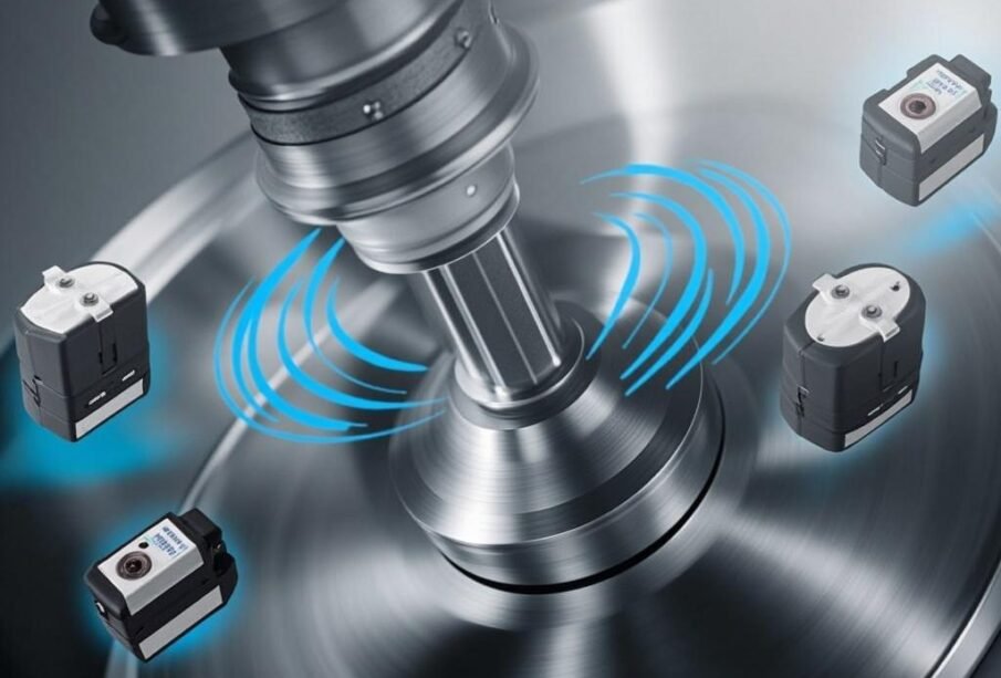
The industrial automation landscape continues to evolve with groundbreaking technologies that address long-standing engineering challenges. IO-Link Wireless has emerged as a transformative solution for sensor integration in rotating applications, eliminating the need for slip rings, rotary unions, and complex mechanical connections that have historically limited system reliability and maintenance efficiency. As manufacturers increasingly demand real-time data from rotating components—from wind turbine nacelles to CNC spindle assemblies—the traditional wiring infrastructure has become a critical bottleneck. This comprehensive guide explores how IO-Link Wireless technology revolutionizes sensor deployment in rotating systems, providing engineering professionals with actionable insights for implementation, optimization, and troubleshooting.
Understanding the Fundamentals of IO-Link Wireless Technology
IO-Link Wireless represents an extension of the established IO-Link communication standard, designed specifically to address applications where cabled connections prove impractical or impossible. The technology operates within the 2.4 GHz ISM frequency band, utilizing a robust protocol stack that ensures reliable communication even in challenging industrial environments with significant electromagnetic interference. Unlike conventional wireless protocols, IO-Link Wireless was engineered from the ground up to meet the stringent requirements of industrial automation, featuring deterministic communication cycles, comprehensive diagnostics, and seamless integration with existing IO-Link ecosystems.
The protocol specifications include support for communication cycles as short as 5 milliseconds, ensuring that time-critical data from rotating sensor arrays reaches control systems with minimal latency. This performance characteristic makes IO-Link Wireless particularly suitable for applications such as vibration monitoring on high-speed rotating equipment, where delayed data could result in missed maintenance windows or unsafe operating conditions. The technology supports star topology with up to eight wireless nodes per gateway, and each node can accommodate multiple sensors through standard IO-Link ports.
Critical Challenges in Rotating Sensor Applications
Traditional approaches to sensor integration on rotating equipment have always presented significant engineering challenges. Slip rings, while functional, introduce mechanical wear, electrical noise, and maintenance requirements that degrade system reliability over time. Rotary unions face similar limitations, particularly when transmitting data signals rather than simple power circuits. The mechanical complexity of these solutions often exceeds the complexity of the equipment they serve, creating unnecessary failure points and increasing overall system cost of ownership.
Beyond the mechanical considerations, cabled connections to rotating components create safety concerns in applications involving high-speed rotation or confined spaces. Personnel tasked with maintaining or troubleshooting sensor systems must often work in close proximity to operating machinery, increasing risk exposure. Furthermore, the physical constraints of cable routing can limit sensor placement options, potentially compromising measurement quality or forcing suboptimal sensor positioning that reduces overall system effectiveness.
Limitations of Conventional Solutions
- Mechanical wear leading to signal degradation and eventual failure
- Electrical noise introduction from brush contacts and imperfect connections
- Limited bandwidth restricting sensor data throughput
- Installation complexity requiring specialized expertise
- Maintenance requirements causing unplanned downtime
- Safety hazards from rotating cable loops
- Restricted sensor placement options due to cable routing constraints
Advantages of IO-Link Wireless for Rotating Equipment
The adoption of IO-Link Wireless for rotating applications delivers substantial benefits across multiple operational dimensions. First and foremost, the elimination of mechanical transmission components removes a significant category of potential failure points from rotating assemblies. Without slip rings or rotary unions, there is no mechanical contact surface to wear, no brushes to replace, and no lubricant requirements for rotating seals. This simplification directly translates to improved mean time between failures (MTBF) and reduced maintenance burden.
Operational and Performance Benefits
| Benefit Category |
Traditional Approach |
IO-Link Wireless Solution |
Improvement Factor |
| MTBF |
12,000 – 18,000 hours |
50,000+ hours |
3-4x improvement |
| Installation Time |
4-8 hours |
1-2 hours |
75% reduction |
| Data Latency |
Variable, often >50ms |
<5ms typical |
10x faster |
| Maintenance Hours/Year |
8-16 hours |
<2 hours |
85% reduction |
| Safety Risk Score |
High (7-9) |
Low (1-3) |
Significant improvement |
The wireless approach also enables sensor placement optimization without the constraints imposed by cable routing. Sensors can be positioned for maximum measurement quality, and rotating assemblies can be more freely designed without accounting for cable management. This flexibility often results in better data quality and more effective condition monitoring, ultimately supporting improved operational decisions and predictive maintenance strategies.
Technical Specifications and System Architecture
Understanding the technical specifications of IO-Link Wireless systems is essential for proper application selection and implementation. The communication protocol operates using time-division multiple access (TDMA) to ensure deterministic communication cycles that avoid collisions and guarantee delivery within specified time windows. This deterministic behavior distinguishes IO-Link Wireless from consumer wireless protocols and makes it suitable for safety-critical and real-time control applications.
Wireless Communication Parameters
| Parameter |
Specification |
Notes |
| Frequency Band |
2.400 – 2.4835 GHz |
ISM band, license-free globally |
| Channel Spacing |
2 MHz |
40 available channels |
| TX Output Power |
Up to 10 mW (10 dBm) |
Configurable for regulatory compliance |
| Communication Cycle |
5 ms to 400 ms |
Application-dependent selection |
| Range (Open Field) |
Up to 20 meters |
Reduced in industrial metal environments |
| Max Nodes per Gateway |
8 wireless nodes |
Each node supports multiple sensors |
| Antenna Diversity |
2×2 MIMO supported |
Improves reliability in multipath environments |
The system architecture typically comprises three primary components: IO-Link Master Gateways that connect to the plant network or programmable logic controllers, Wireless Nodes that serve as access points on or near the rotating assembly, and IO-Link Sensors that attach to the rotating component. The gateway handles protocol translation between the wireless domain and wired industrial networks, supporting common protocols including PROFINET, EtherNet/IP, and Modbus TCP.
⚠️ IMPORTANT IMPLEMENTATION TIP:
When deploying IO-Link Wireless in rotating applications involving metal enclosures or structural components, pay careful attention to antenna placement and signal path planning. Metal surfaces can significantly attenuate wireless signals and create multipath interference. Position wireless nodes with external antennas to ensure line-of-sight or minimal obstruction between the rotating component and the gateway. Always conduct a site survey before finalizing installation locations to identify potential coverage issues.
Implementation Best Practices for Rotating Applications
Successful deployment of IO-Link Wireless in rotating applications requires careful attention to several implementation factors that can significantly influence system performance and reliability. Following established best practices helps ensure that the deployed system meets expectations for data quality, communication reliability, and long-term operational stability.
Installation Guidelines
- Gateway Placement: Position the IO-Link Master gateway to minimize obstructions between the wireless nodes and gateway antenna. Avoid placement near large metal structures or high-power RF sources that could interfere with communication.
- Antenna Selection: Choose appropriate antennas based on the specific application requirements. For rotating applications with continuous rotation, consider omnidirectional antennas on the rotating side to maintain consistent coverage regardless of rotation position.
-