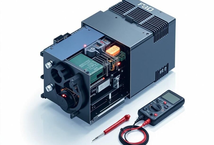
Variable Frequency Drives (VFDs) are essential components in modern industrial and commercial applications, providing precise motor control and significant energy savings. However, like any sophisticated electronic equipment, VFDs can experience faults and operational issues that require systematic troubleshooting. This comprehensive guide addresses the most common VFD problems, their diagnostic procedures, and practical solutions that maintenance technicians and engineers can implement to restore optimal drive performance and minimize costly downtime.
Understanding VFD Fault Codes and Diagnostics
Modern VFDs are equipped with sophisticated self-diagnostic systems that display specific fault codes when abnormalities occur. Understanding these codes is the first step in effective troubleshooting. Most manufacturers use standardized fault categories, including overcurrent, overvoltage, undervoltage, overtemperature, and communication faults. When a fault occurs, the drive’s keypad typically displays a code such as “OC1” for acceleration overcurrent or “OV” for overvoltage condition. Always consult your specific VFD manufacturer’s documentation, as fault code designations vary between brands like Siemens, ABB, Rockwell, and Schneider Electric.
Before beginning any troubleshooting procedure, ensure you have reviewed the drive’s event history log, which records the sequence of faults and operating parameters at the time of failure. This historical data provides invaluable insights into whether the fault was an isolated incident or part of a recurring pattern that indicates deeper systemic issues.
Common Overcurrent Faults and Resolutions
Overcurrent faults are among the most frequently encountered VFD problems and typically indicate issues with the motor, wiring, or drive parameters. These faults occur when the output current exceeds the drive’s safe operating limits, triggering protective shutdown mechanisms.
Acceleration Overcurrent (OC1/OC2)
This fault commonly occurs during motor startup or speed changes and is usually caused by excessive load torque, incorrect acceleration time settings, or motor winding problems. To diagnose this issue, first verify that the mechanical load is not jammed or binding. Check the motor windings for shorts or ground faults using a megohmmeter. Review the acceleration time parameter and increase it if the load requires longer ramp-up periods. Additionally, verify that the motor nameplate data has been correctly programmed into the VFD, as incorrect voltage or horsepower settings can cause excessive current draw during acceleration.
Deceleration Overcurrent
Deceleration overcurrent faults typically result from excessive regenerative energy being returned to the drive when the motor is braking. This is particularly common in applications with high inertia loads such as fans, pumps, or conveyors. Solutions include extending the deceleration time, installing a dynamic braking resistor to absorb regenerative energy, or enabling the drive’s built-in overvoltage suppression functions.
⚠️ IMPORTANT SAFETY WARNING:
Before performing any troubleshooting or maintenance on VFD systems, always disconnect input power and wait the specified discharge time (typically 5-10 minutes) as capacitors can retain dangerous voltage levels. Always use appropriate Personal Protective Equipment (PPE) including insulated gloves and safety glasses. Never bypass or defeat safety interlock devices. Failure to follow proper lockout/tagout procedures can result in severe injury or death from electrical shock.
Overvoltage and Undervoltage Troubleshooting
Voltage-related faults indicate problems with the power supply quality or drive’s voltage regulation systems. These issues can significantly impact drive reliability and longevity if not properly addressed.
Overvoltage Faults (OV)
Overvoltage conditions occur when the DC bus voltage exceeds safe thresholds, typically above 800V for 480V drives. Common causes include:
- Regenerative energy from braking loads exceeding drive capacity
- Input power voltage exceeding drive specifications
- Loose or poor power connections causing voltage spikes
- Incorrect mains voltage selection settings
- Harmonic distortion from other equipment on the same supply
Undervoltage Faults (UV)
Undervoltage conditions can cause erratic motor operation and premature drive failure. The following table summarizes common causes and diagnostic steps:
| Fault Condition |
Possible Causes |
Diagnostic Action |
| Low Input Voltage |
Utility supply issues, undersized transformers |
Measure line-to-line voltage at drive terminals |
| Sags and Dips |
Large loads switching on/off, motor starting |
Monitor voltage with power quality analyzer |
| Loose Connections |
Vibration, thermal cycling, poor installation |
Inspect and torque all power connections |
| Phase Loss |
Open breaker, failed fuse, wiring issue |
Check all three phases with multimeter |
Overtemperature Issues and Thermal Management
VFD overtemperature faults indicate that the drive’s internal components are operating beyond their designed thermal limits. Prolonged thermal stress is one of the leading causes of premature VFD failure, making temperature issues critical to address promptly. The drive’s heat sink temperature is continuously monitored, and shutdown typically occurs when temperatures exceed approximately 90-100°C depending on the manufacturer.
Common Causes of Overtemperature
When troubleshooting temperature-related faults, consider these factors in your diagnostic approach:
- Cooling System Failure: Check that cooling fans are operational, clean from debris, and rotating at correct speeds. Failed fans should be replaced immediately. Inspect heat sinks for dust accumulation and clean with dry compressed air.
- Ambient Temperature: Verify that the enclosure ventilation is adequate and the ambient temperature stays within the drive’s rated specifications, typically 0-40°C for most industrial VFDs.
- Overloading: Confirm that the motor load current does not consistently exceed the drive’s rated current capacity. Consider sizing up the drive if the application requires continuous operation near maximum capacity.
- Altitude Derating: VFDs lose cooling efficiency at higher altitudes. If installed above 1000 meters, consult manufacturer guidelines for proper derating factors.
- Blocked Airflow: Ensure minimum clearances around the drive are maintained according to manufacturer specifications, typically 50-100mm on all sides.
Motor and Wiring-Related Faults
Many VFD faults originate from motor or wiring issues rather than problems with the drive itself. Systematic testing of these components can identify problems before unnecessary drive replacements are made.
| Test/Inspection |
Procedure |
Acceptable Values |
| Motor Winding Resistance |
Measure resistance between all phase pairs |
Values should be balanced within 2% |
| Insulation Resistance |
Megger test phase to ground |
Greater than 1 megohm for new motors |
| Ground Fault |
Measure continuity from motor frame to ground |
Low resistance indicates ground fault |
| Cable Integrity |
Inspect cable insulation, check for damage |
No visible damage, proper shielding intact |
| Motor Rotation Test |
Temporarily jog motor and verify direction |
Correct rotation per process requirements |
Communication and Parameter Faults
In modern automated systems, VFDs often communicate with PLCs and other controllers via industrial networks such as Profibus, DeviceNet, EtherNet/IP, or Modbus. Communication faults can cause complete system shutdowns and require specialized troubleshooting approaches.
Network Communication Troubleshooting
When communication faults occur, verify the following systematically:
- Check network cable integrity and shielding; damaged cables are the most common cause of communication failures
- Verify proper termination resistors are installed at network ends
-
Post Views: 1